Results 1 to 7 of 7

Thread: Looking for a vector file of a globe in flat pattern

  1. #1

    Help Looking for a vector file of a globe in flat pattern

    I am looking for a vector file of a globe that I need to build. The file should look like this. I will cut out the pattern from steel with a CNC plasma cutting table and wrap it around a framework. Does anyone have a file like this or can you direct me in the right direction? Almost any vector file will work however I mostly us DXF. or CorelDrawX6.


    Click image for larger version. 

Name:	globe flat pattern.png 
Views:	293 
Size:	42.5 KB 
ID:	73168

  2. #2
    Guild Novice
    Join Date
    Dec 2014
    Location
    Minneapolis, Minnesota USA
    Posts
    8

    Default

    This powerpoint by Daan Strebe (one of the top experts on map projections) has some very brief summaries of criteria in choosing a globe gore projection and rendering: http://mapthematics.com/Downloads/Gores.pdf

    This also may be useful:http://www.progonos.com/furuti/MapPr...t/projInt.html

    I would suggest working with Natural Earth's dataset (http://naturalearthdata.com), and render each gore separately. I can do this in AvenzaMaPublisher (resulting in a PDF, AI, or EPS file, or possibly DXF) if you don't find someone else, pretty inexpensively. Basically you want to choose how many gores you want to use, divide up the the earth into sections, evaluate how much if any overlap you want between gores, and then render each section with a polyconic projection.

    I did a project with someone using a laser cutter to cut wood or steel with recently, and the problem we had was that the cutter had a diameter to it that ended up wrecking key bits of coastal detail. We ended up with a solution that involved expanding the coastline by half the diameter of the cutting tool, which worked OK. The client got all upset when I told him I needed to charge him real money for the third or fourth hand-corrected rendering. Very odd. Anyway, I'm happy to talk about this with you. You can contact me at http://incasellc.com/nat/contact-nat-case/

  3. #3
    Software Dev/Rep Hai-Etlik's Avatar
    Join Date
    May 2009
    Location
    48° 28′ N 123° 8′ W
    Posts
    1,333
    Blog Entries
    1

    Default

    It sounds like you might be better off doing projections on a contiguous landmass basis rather than regular gores. It's more work to figure out, but less in terms of fabrication as it reduces the number of parts and seams between them.

  4. #4
    Guild Expert johnvanvliet's Avatar
    Join Date
    Jul 2012
    Location
    N 42.39 W 83.44
    Posts
    1,091
    Blog Entries
    4

    Default

    for the Earth

    your final output needs to be a SVG

    for a black and white image that is somewhat easy

    start with the STRM or GTPO30 or the Gmted 2010 data

    for the GMTED 2010 is not the full planet
    i have a reworked full 90 north to 90 south here
    Ds15.zip-- 855 Meg
    https://drive.google.com/open?id=0B6...YVU&authuser=0

    use sealevel for the black and white save as a ppm image ( netppm)
    and use netppm's "ppmglobe" to make the gores
    Code:
    ppmglobe 6 InputImage.ppm > OutputImage.ppm
    and you get


    then a bit trace in inkscape to output a SVG

    the strm is here
    http://dds.cr.usgs.gov/srtm/version2_1/

    a bit easier to use the nasa Bluemarble topo data
    http://mirrors.arsc.edu/nasa/topography/

    small 5400x2700 jpg preview image
    http://mirrors.arsc.edu/nasa/topogra....5400x2700.jpg


    this water mask is ALREADY black and white only -- might work
    -- small preview
    http://mirrors.arsc.edu/nasa/landmas....5400x2700.png
    http://mirrors.arsc.edu/nasa/landmask/


    How big is this globe ?
    1 Meter diameter ?
    10 Meters diameter ?
    20 Meters diameter ?

    or something table top size like 30 CM ?


    natcase701 has a good point
    the cutter OD dia. !!!!

    just like in casting the model has to be made with a "shrinkage " ruler

    the width of the plasma cut will NEED to be accounted for

    Do you have access to Autocad ( very pricy - used car pricy)
    Last edited by johnvanvliet; 05-06-2015 at 12:19 AM.
    --- 90 seconds to Midnight ---
    --------

    --- Penguin power!!! ---


  5. #5

    Default

    Thanks for the all the replies. This globe is going to be 2.5 meters in diameter. The company doing the welding will is building a metal frame work with 12 ribs. I will be cutting the land objects and they will weld them to the frame.
    I think I want to use this map as a starting point.
    http://mirrors.arsc.edu/nasa/landmas...k.5400x2700.pn
    But how does that work if I just cut it into gores. What happens if I loose critical details. Does that not change the shape of some of the land masses?

    The plasma cutter kerf is not a problem. I have software that take a vector file and offsets the cut line by half the width of the kerf. Also a have an AutoCad type CAD program. How would that make this project simpler?

    Doug

  6. #6
    Guild Expert johnvanvliet's Avatar
    Join Date
    Jul 2012
    Location
    N 42.39 W 83.44
    Posts
    1,091
    Blog Entries
    4

    Default

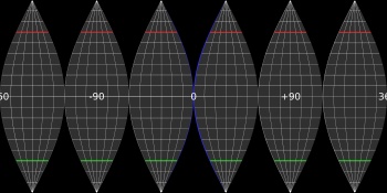
    for a globe with a diameter of 2.5 M is a circumference of 7.85 Meters
    a base image like the one above with a size of 5400x2700 pixels is 687.89 px/M or 6.8789 pixels per CM
    might be a bit too low resolution ??? maybe


    netppm
    http://netpbm.sourceforge.net/
    should be installed by default on every linux and apple computer and maybe on windows ( postcstipt can use it in printing )
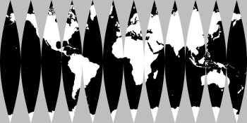
    remapping it into 12 Gores ( or 24 )
    -- convert the png ( portable network graphics ) to a ppm ( portable pixel map )
    Code:
    ppmglobe -background=gray 12 world.oceanmask.5400x2700.ppm > 12.ppm
    for a black background remove "-background=gray" from the command
    -- small downsize

    from there inkscape
    https://inkscape.org/en/
    can convert it to a SVG

    autocad also should be able to import a png or a bitmaped image and save as a svg
    or as a 3d mesh format say the white as one unit in mesh height higher that the black

    blender can even do that and maybe even "Anam8or"

    the above is the EASY part

    converting that to one of the file formats that are needed for the cutter ?
    the people that own the cutter should be able to do that
    the above image would be basically the same as a blue-print
    --- 90 seconds to Midnight ---
    --------

    --- Penguin power!!! ---


  7. #7
    Banned User
    Join Date
    Jul 2014
    Location
    Traverse City, Michigan, USA
    Posts
    2,547

    Default

    You know, I was thinking about this last night and how I would go about it.

    For all the high-tech solutions you are looking at here, I'd start with about a half dozen of these

    http://www.amazon.com/Learning-Resou...ds=child+globe

    and a pair of scissors, and start cutting and flattening, to see just exactly what distorts, where you can cut, bend, and re-weld to preserve the important details, and figure out what shape pieces you need.

Posting Permissions

  • You may not post new threads
  • You may not post replies
  • You may not post attachments
  • You may not edit your posts
  •